Combinational Logic Circuits
in CS 101
We understand how to convert our real-world (numbers, text, images) into binary, but how does a computer understand binary?
Boolean Algebra
In the 1854, George Boole developed a set of operators and laws (an algebra) for variables that can have just two states (true and false). Boolean algebra is used to create, analyze, and use digital circuits (aka logic circuits) because zeros and ones are interpreted as signals in a computer.
Boolean Algebra Rules
These are the important rules in Boolean algebra.
- Variables can have only two values (
1=HIGH=trueand0=LOW=false). - The complement (aka the
NOToperation) of a variable is represented by a comma ('). For example, the complement of variableAis represented asA'. Therefore, ifAoriginally equals0, thenA'equals1(flip the value). - The
ORoperation is represented by a+(plus) sign between two variables. For example,A OR B OR Cis written asA + B + C. - The
ANDoperation is represented by a·(dot) sign between two variables. For example,A AND B AND Cis written asA · B · C. Sometimes, this operation is inferred, so we can instead omit the dot and writeABC.
Boolean Laws
There are six laws in Boolean algebra.
- The commutative law:
A + B = B + AorA · B = B · A. - The associative law:
(A · B) · C = A · (B · C)'or(A + B) + C = A + (B + C)' - The distributive law:
A · (B + C) = A · B + A · C - The AND law:
A · 0 = 0A · 1 = AA · A = AA · A' = 0
- The OR law:
A + 0 = AA + 1 = 1A + A = AA + A' = 1
- The NOT law (aka law of inversion):
A'' = A
DeMorgan’s Theorem
Simply, (A · B)' is equal to (A' + B').
Logic Gates
Logic gates (aka transistor gates) are the basic building blocks of any digital system. These gates have one or more inputs, but only one output. However, the relationship between the inputs and output must be based on a certain logic (hint: Boolean algebra). Based of Boolean algebra, the gates are accordingly named AND gates, OR gates, NOT gates, and so on. The following chart by braulio777 shows the symbols, expressions, and truth tables we use to denote these gates.

Combinational Circuits
We combine different gates to make various combinational circuits. For example, (A · B) · C can be drawn as (images by Jimb0)
With three inputs, we can make 23 = 8 combinations. This number grows exponentially as 2n, where n is the number of inputs. So, a 4-input circuit has 24 = 16 possible combinations, 5 inputs would produce 32 outputs, and so on.
Because the above combinational circuit has 3 inputs (which we name A, B, and C), we can create a three-variable truth table (4 columns: 3 for inputs, and 1 for the output).
	A	B	C	(AB)C
	0	0	0	= 0
	0	0	1	= 0
	0	1 	0	= 0
	0 	1 	1	= 0
	1	0 	0	= 0
	1 	0 	1 	= 0
	1 	1 	0	= 0
	1 	1 	1	= 1
If we attach a light (an LED) at the end of our circuit, it would only turn on when all three inputs are on (= 1).
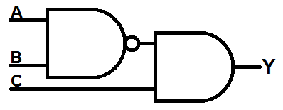
First, try to derive the boolean expression from the following diagram, and create its truth table.
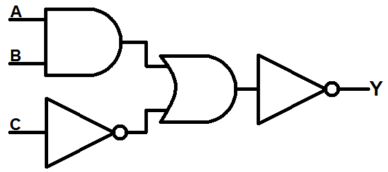
- We can see that inputs
AandBare connected through anANDgate. This is= A · B. - Input
Cgoes through anNOTgate. The output of theNOTis written as= C'. - Then,
(A · B)andC'become inputs to anORgate. Their output is= (A · B) · C' - Finally, the output of the previous
ORgate becomes negated. The output of the finalNOTgate is= ((A · B) · C')'
We can simplify this by using the boolean laws we previously discussed.
((A · B) · C')'becomes(A · B · C')'due to the associative law(A · B · C')'becomesA' + B' + C''due to DeMorgan’s theoremA' + B' + C''becomesA' + B' + Cdue to the inversion law- Optionally, we can revert this to see how it matches the diagram simplification into ((A · B)’ · C) by DeMorgan’s theorem backwards. However, this is not considered the simplest boolean expression.
The corresponding truth table is:
	A	B	C	A' + B' + C
	0	0	0	= 1
	0	0	1	= 1
	0	1 	0	= 1
	0 	1 	1	= 1
	1	0 	0	= 1
	1 	0 	1 	= 1
	1 	1 	0	= 0
	1 	1 	1	= 1
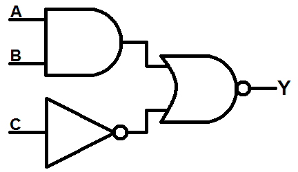
To simplify this diagram from the diagram alone, we can repeat these same steps. The last two gates are a OR followed by a NOT gate. We can combine these to make an NOR gate:
Then, let’s apply DeMorgan’s theorem by combining the NOT with the NOR gate, turning it into an AND gate. But this creates NOT gates on both inputs:
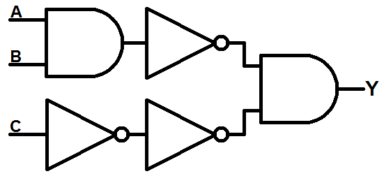
Finally, the two NOT gates on input C would cancel each other out. The NOT gate on the first AND’s output can be combined with the AND to get:
This is simplest diagram of these boolean expression because it used the least amount of gates. Previously, when we simplified this using only boolean algebra we got an answer of A' + B' + C. In a diagram, this expression, as is, requires 4 gates (2 NOTs and 2 ORs).
Practice
Prove DeMorgan’s theorem by drawing the circuits and truth tables for (A · B)' and for A' + B'.
Additional Resources
- logic.ly: create and run your own combinational circuits
- AND OR NOT Logic Gates Explained - Computerphile
- How do logic gates store information? - Computerphile
- Sequential Circuits - Flip Flops, Latches, & Memory - Computerphile